
In the ever-evolving world of electronics and signal analysis, precise measurement instruments play a crucial role in diagnosing, testing, and optimizing circuits. Whether you’re a seasoned engineer or an enthusiastic hobbyist, mastering tools like an isolated USB oscilloscope, understanding oscilloscope probe compensation, and decoding protocols such as I2C can significantly enhance your troubleshooting and design capabilities.
This article delves into four essential topics that bridge the gap between theoretical knowledge and practical application. First, we explore the fundamentals of measurement instruments and their significance in modern electronics. Next, we examine the advantages of an isolated USB oscilloscope, a versatile tool for safe and accurate signal analysis. Then, we demystify oscilloscope probe compensation—a critical yet often overlooked aspect of ensuring measurement accuracy. Finally, we break down the process of decoding the I2C protocol, a widely used communication standard in embedded systems.
By the end of this guide, you’ll gain a deeper understanding of these key concepts, empowering you to make informed decisions in your projects. Let’s begin by exploring the foundational role of measurement instruments in electronic diagnostics and design.
What Are the Key Measurement Instruments in Electronics?
Measurement instruments are the backbone of electronics, enabling engineers and technicians to analyze, debug, and validate circuit behavior with precision. Without these tools, diagnosing faults or verifying performance would be nearly impossible. From multimeters to spectrum analyzers, each instrument serves a unique purpose in capturing and interpreting electrical signals.
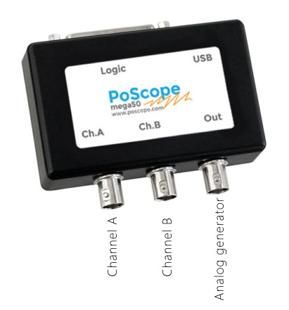
Among the most essential measurement instruments is the oscilloscope, a device that visualizes voltage signals over time. Oscilloscopes come in various forms, including benchtop, handheld, and USB-based models, each suited for different applications. Another critical tool is the digital multimeter (DMM), which measures voltage, current, and resistance with high accuracy. For frequency-domain analysis, spectrum analyzers are indispensable, helping engineers examine signal harmonics and noise characteristics.
Additionally, logic analyzers play a vital role in digital systems, capturing and decoding multiple signal lines simultaneously—ideal for debugging communication protocols like SPI, UART, and I2C. Power supplies and function generators are also fundamental measurement instruments, providing stable voltage outputs and test waveforms for circuit stimulation.
The choice of measurement instruments depends on the application. For high-voltage environments, an isolated USB oscilloscope ensures safety by galvanically separating the measurement side from the computer. Meanwhile, high-speed designs may require advanced oscilloscopes with bandwidths exceeding 1 GHz to accurately capture fast signal transitions.
Understanding these measurement instruments is the first step toward efficient circuit analysis. In the next section, we’ll explore the advantages of an isolated USB oscilloscope and why it’s a preferred choice for many engineers.
Why Should You Use an Isolated USB Oscilloscope?
In modern electronics, safety and flexibility are paramount when taking measurements, especially in high-voltage or floating ground applications. This is where an isolated USB oscilloscope becomes an indispensable tool. Unlike traditional oscilloscopes that share a common ground with the host computer, an isolated USB oscilloscope provides galvanic separation between the measured circuit and the PC, preventing ground loops and protecting both the user and the equipment from potential hazards.
One of the key advantages of an isolated USB oscilloscope is its ability to measure signals in circuits where the ground reference is not at earth potential. For example, when working with motor drives, power converters, or offline power supplies, a non-isolated oscilloscope could create a short circuit through its ground connection, damaging the device or even posing an electrical shock risk. The isolation barrier in a USB oscilloscope eliminates this danger, allowing safe probing of high-side MOSFETs, current shunts, and other floating voltage points.
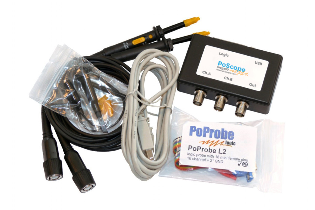
Another benefit is portability. Since an isolated USB oscilloscope relies on a computer for processing and display, it is often more compact and lightweight than a benchtop model. This makes it ideal for fieldwork, educational environments, or situations where lab space is limited. Many models also include advanced features such as high-resolution ADCs, deep memory, and protocol decoding, rivaling the performance of larger oscilloscopes.
Additionally, isolated USB oscilloscopes often come with powerful software that enables remote monitoring, automated measurements, and data logging—capabilities that are particularly useful for long-term testing and analysis. Some even support battery operation, further enhancing their versatility in scenarios where AC power is unavailable.
Despite these advantages, users must still pay attention to proper probing techniques, including oscilloscope probe compensation, to ensure accurate measurements. In the next section, we will explore why probe compensation is critical and how to perform it correctly.
Why Is Oscilloscope Probe Compensation Critical for Accurate Measurements?
When working with an oscilloscope—whether it’s a high-end benchtop model or an isolated USB oscilloscope—proper probe setup is essential for signal integrity. One of the most crucial yet often overlooked steps is oscilloscope probe compensation, a calibration process that ensures the probe accurately transmits the signal without distortion. Skipping this step can lead to misleading waveforms, incorrect rise-time measurements, and flawed data interpretation.
Oscilloscope probe compensation is necessary because passive voltage probes (typically 10x attenuation probes) have an inherent capacitance that interacts with the oscilloscope’s input capacitance. If these capacitances are mismatched, the probe will either overcompensate (causing overshoot and ringing) or undercompensate (resulting in sluggish, rounded edges). Most oscilloscopes provide a built-in calibration square wave signal, usually 1 kHz, specifically for probe adjustment.
To perform oscilloscope probe compensation, connect the probe to the reference output and attach the tip to the square wave signal. Then, using a small screwdriver, adjust the compensation trimmer capacitor on the probe until the displayed waveform shows clean, square edges without overshoot or rounding. A properly compensated probe will faithfully reproduce the calibration signal, ensuring that subsequent measurements are accurate.
This process is especially important when using high-bandwidth probes or when measuring fast digital signals, where even minor miscompensation can distort pulse widths and timing relationships. Additionally, if multiple probes are used simultaneously, each one must be individually compensated, as variations in probe capacitance can lead to inconsistent readings across channels.
Failing to perform oscilloscope probe compensation can be particularly problematic when working with precision circuits or high-speed communication protocols like I2C, where signal fidelity is critical. In the next section, we will explore how to decode the I2C protocol using an oscilloscope, a task that relies heavily on accurate signal capture.
How Can You Decode the I2C Protocol Using an Oscilloscope?
The I2C protocol is a widely used serial communication standard in embedded systems, connecting microcontrollers, sensors, and memory devices. While logic analyzers are often the go-to tool for decoding I2C, a well-configured oscilloscope—especially an isolated USB oscilloscope with protocol decoding capabilities—can be just as effective for troubleshooting and validation.
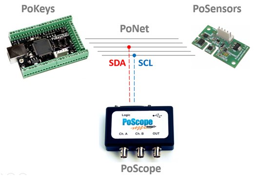
For decoding I2C protocol, you first need to capture the physical signal lines: the serial data line (SDA) and the serial clock line (SCL). Since I2C is bidirectional and open-drain, pull-up resistors are required, and signal integrity is critical. This is where proper oscilloscope probe compensation becomes essential—any distortion in the waveform could lead to misinterpretation of start conditions, address bits, or data bytes.
Most modern oscilloscopes, including advanced isolated USB oscilloscopes, feature built-in I2C decoding. After connecting the probes to SDA and SCL, enable the protocol decoding function and configure the settings to match the I2C bus speed (standard mode: 100 kHz, fast mode: 400 kHz, etc.). The oscilloscope will then interpret the raw waveforms into readable hexadecimal or binary data, displaying address, read/write operations, and payload bytes directly on the screen.
Decoding I2C with an oscilloscope is particularly useful for real-time debugging, as it allows you to correlate signal anomalies (like noise or glitches) with specific transactions. For example, if a sensor isn’t responding, you can verify whether the correct address was sent or if acknowledgments (ACK/NACK) are being properly received. Some oscilloscopes even support triggering on specific I2C events, such as a repeated start condition or a particular device address, making it easier to isolate issues.
While dedicated measurement instruments like logic analyzers offer deeper buffer memory for long captures, an oscilloscope provides the advantage of analog signal inspection—crucial for diagnosing signal integrity problems that could disrupt I2C communications. In the final section, we’ll summarize how these techniques integrate into a cohesive measurement strategy.
Mastering Measurement Techniques for Reliable Electronics Debugging
From foundational measurement instruments to advanced protocol analysis, each tool and technique we’ve explored plays a vital role in modern electronics troubleshooting and design. The right measurement instruments—oscilloscopes, multimeters, logic analyzers—form the backbone of any engineer’s toolkit, enabling precise signal observation and validation. Among these, the isolated USB oscilloscope stands out as a versatile solution, combining portability with robust isolation for safe floating measurements in power electronics and other high-voltage applications.
We also examined the critical importance of oscilloscope probe compensation, a simple yet often neglected step that ensures signal fidelity. Whether using a benchtop oscilloscope or an isolated USB model, proper probe adjustment prevents distorted waveforms and misleading data—especially crucial when working with high-speed digital signals or sensitive analog circuits.
Finally, decoding the I2C protocol demonstrated how modern oscilloscopes bridge the gap between analog signal integrity and digital protocol analysis. By capturing and interpreting SDA and SCL lines, engineers can quickly diagnose communication errors, validate sensor data, and verify timing relationships—all while maintaining visibility into potential analog signal issues that a pure logic analyzer might miss.
Together, these techniques form a comprehensive approach to electronics measurement. By selecting the right tools, applying proper calibration methods like oscilloscope probe compensation, and leveraging advanced features such as I2C decoding, engineers can tackle increasingly complex designs with confidence. As technology evolves, so too must our measurement strategies—ensuring accuracy, efficiency, and safety in every circuit we test.